Latest Posts
STM32 Demo Board: Getting Started and Advanced Preparation
Essentials for Beginners
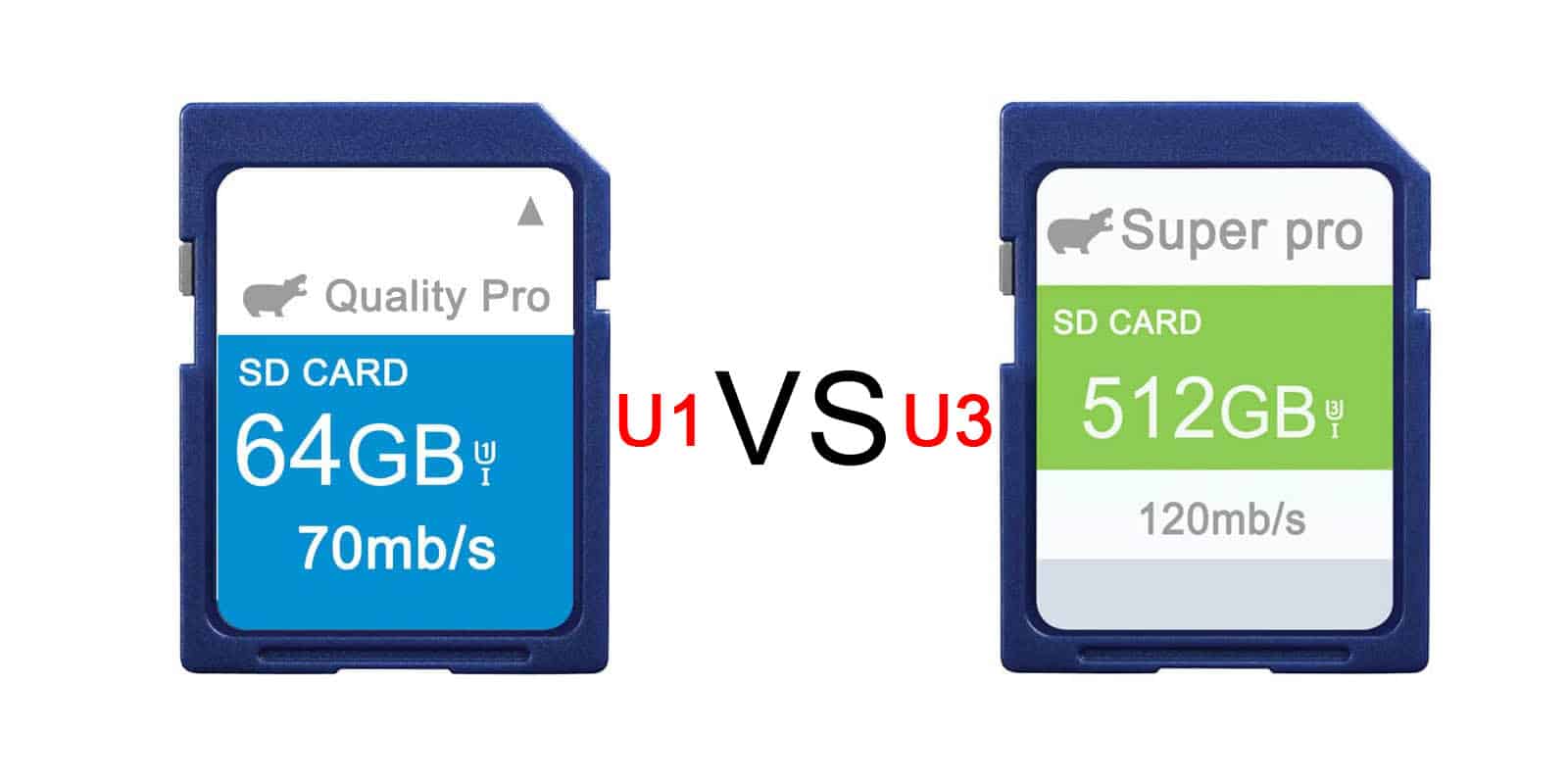
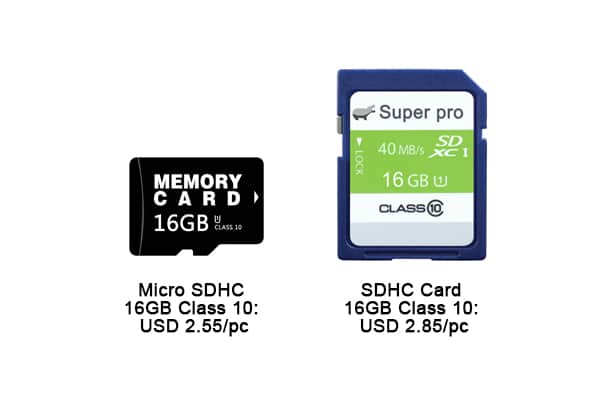
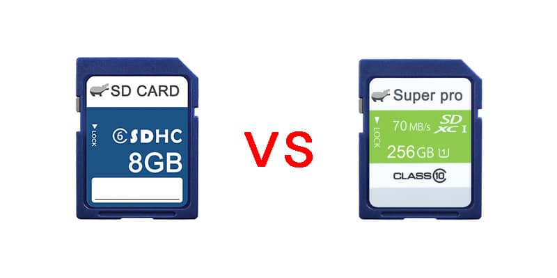
The development board may look simple, but many people are discouraged at the step of how to use it. Today, I’m here to teach you how to solve the problems of getting started with single-board computers (SBCs), taking the Orange Pi Zero 3 as an example. How many steps are generally needed to use an Orange Pi? First, prepare a USB Type-C power cable, a charger with at least 5V 2A , a memory card with a capacity of at least 8GB, and a Micro HDMI cable to connect to a monitor or TV to display information from the development board. Some Demo Boards may have DP or mini HDMI interfaces, or standard HDMI interfaces, and you will need to purchase the corresponding cables to match your development board.
If your monitor doesn’t have a DP interface, you can opt for a DP-to-HDMI cable. However, as of now, there are still few Demo Boards without an HDMI interface. We also need to prepare a keyboard, and if you’re using a desktop like Windows, you’ll also need a mouse. If your Demo Board doesn’t have WiFi or Bluetooth, you’ll need to provide an Ethernet cable and access to the internet. Finally, you’ll need a working computer with a USB port. If your Demo Board has onboard eMMC, you won’t need to prepare a TF card. If your development board also has an M.2 SSD interface and you happen to want to use an SSD, you’ll also need to prepare an SSD.

After preparing all this hardware, the next step is to install the system. Installing a system on a development board is simpler than on a computer. First, find the official website of the development board and download the system you want to use onto your computer. Then you can proceed to install the system. There are several installation methods, which differ depending on which storage medium you want to install the system on, such as a memory card, eMMC, or SSD. Installing on a memory card is the simplest.
Here, pay attention to the protocols and sizes of the SSDs supported by the development board. There are two protocols: M.2 SATA SSD interfaces and NVMe SSD interfaces. In terms of size, they vary based on length with M.2 2230, 2242, and 2280 being the main sizes. You need to choose the SSD based on the protocols and slots provided by the development board.
Pay attention to the protocols and sizes of the SSDs supported by the development board. There are two protocols: M.2 SATA SSD interfaces and NVMe SSD interfaces. In terms of size, they vary based on length with M.2 2230, 2242, and 2280 being the main sizes. You need to choose the SSD based on the protocols and slots provided by the development board.
Flashing the system to the SSD is also done using the Ralink development tools, with the difference being the configuration file; just select PCI and the system installation is complete.
Once the hardware and software are ready, plug in the HDMI and power cables and wait for the system to boot. Note that some Demo Boards have a switch, which could be a selection switch or a push-button switch, so you should refer to the documentation for operation. Generally, the system will start automatically when powered, and if it doesn’t start automatically, check if the switch hasn’t been pressed.
Professional Player Essentials
Some commonly used tools in electronic design, which can also be considered essential, start with soldering. First is the soldering iron, which comes in temperature-controlled and adjustable temperature models. A temperature-controlled soldering iron is similar to this type where you plug it in and it directly reaches a fixed temperature.
The higher the wattage, the faster it heats up. An adjustable temperature soldering iron is similar to this type, generally adjustable between 200 to 500 degrees, because some chips have requirements for soldering temperature and cannot withstand high temperatures, so this adjustable temperature soldering iron has a broader range of applications. When using a soldering iron, you need a soldering iron stand, which comes in various types and can be chosen based on personal preference.
Soldering Iron
When using a soldering iron, you need to frequently clean the tip, which is where the soldering sponge comes in, similar to the one in the picture. Then there’s solder, which comes in leaded and lead-free varieties, with different tin content and wire gauges. I personally often use 63/37 tin with a 0.6mm diameter.
There’s also flux in the form of solder paste or rosin, solder paste is similar to the one in the picture. Rosin is similar to this type of desoldering pump. When soldering and needing to remove some solder, a desoldering pump is needed, which looks like the one in the picture. Then there’s the solder wick, which is this type of perforated board, but it’s basically disposable, and after soldering, it’s hard to clean and reuse.
Breadboard
A breadboard is a type of board where you can insert components and perform some debugging and testing.
Dupont Wire
Dupont wires are used to connect two endpoints of a test circuit, generally divided into male and female ends, with the female end being this type with holes and pins. Choose according to your needs, and the male end looks like this, which is also a commonly used small tool in testing circuits. You can insert Dupont wires or their corresponding sockets, and this is the socket corresponding to the pins.
Tinned Wire
Then there’s tinned wire, also known as enameled wire, which comes in different thicknesses and lengths, and is also commonly used in testing to connect two solder points.
Others
Tweezers are used as conductors for adding small precision components, and small surface-mount resistors and capacitors are commonly used. Flush cutters are used for trimming, similar to this type, generally for cutting the leads of some soft components. To strip the outer skin of wires, you need wire strippers, which are also commonly used.
A multimeter is also the most commonly used tool for measuring current, voltage, resistance, capacitance, and continuity, which can be said to be the most commonly used tool in electronic design.
Conclusion
Then there are some tools that are not commonly used at the beginning of electronic design, but can be added later when needed, such as hot air guns, needle-nose pliers, screwdrivers, some fixtures, heat shrink tubes, regulated power supplies, oscilloscopes, and logic analyzers. Basic electronic design may not need these for the time being.
This article introduces how to choose and use STM32. It is hoped that through the introduction in this article, beginners can understand the basic concepts and entry guide of STM32 for subsequent learning and application. If you don’t understand embedded systems, come to me. Thank you, everyone.


Leave a comment